
Silica Sand Washer Flow Chart
Process flow diagram for the production of semiconductor grade (electronic grade) silicon. Single Crystal Silicon Wafer Fabrication The silicon wafers so familiar to those of us in the semiconductor industry are actually thin slices of a large single crystal of silicon that was grown from melted electronic grade polycrystalline silicon.
 WhatsAppGet PriceGet A Quote
Mentioned cement production people will say "two grinding burn",that means cement production process mainly includes three stages: raw meal preparation, clinker burning and cement grinding. The cement manufacturing process flow chart is shown as follows:
WhatsAppGet PriceGet A Quote
Good control of the morphology, particle size, uniformity and dispersity of mesoporous silica nanoparticles (MSNs) is of increasing importance to their use in catalyst, adsorption, polymer filler, optical devices, bio-imaging, drug delivery, and biomedical applications.
WhatsAppGet PriceGet A Quote
Silica sand mining process equipment flow process Crushing processing sandstone sandstone crushing processing technology at present mainly has the following kinds. 1, crushing process directly.Its technological process is: the run of mine ore – grizzly – jaw crusher crushing and screening to cone crushing and screening, more paragraphs to roll the crushing and screening – products.
WhatsAppGet PriceGet A Quote
hotelturkuaz.nl
WhatsAppGet PriceGet A Quote
A general flow chart for sol-gel process which leads to the production silica using silicon alkoxides (Si(OR) 4) is shown in Figure 2. Figure 2 Flow chart of a typical sol-gel process.
WhatsAppGet PriceGet A Quote
Commercially produced glass can be classified as soda-lime, lead, fused silica, borosilicate, or 96 percent silica. Soda-lime glass, since it constitutes 77 percent of total glass production, is discussed here. Soda-lime glass consists of sand, limestone, soda ash, and cullet (broken glass). The
WhatsAppGet PriceGet A Quote
Fiberglass Production Flowchart . Glass fibers are composed of oxides of silica. Glass is an inorganic Flow Chart of Yarn Path for Circular Knitting
WhatsAppGet PriceGet A Quote
hotelturkuaz.nl
WhatsAppGet PriceGet A Quote
In this study, ash from sugarcane waste was used in the synthesis of biosilica using alkaline extraction followed by acid precipitation. Different parameters that could influence the silica particle synthesis were evaluated. The ash and synthesized biosilica were characterized by a combination of spectroscopic and chemical techniques such as XRD, XRF, SEM, particle size analyser, N2
WhatsAppGet PriceGet A Quote
grinding mill flow chart crushing india – Crusher Company. silica sand production line … flow chart diagram jaw crusher … stone crusher plant flow chart images india #8230; bauxite ore processing plant, … »More detailed
WhatsAppGet PriceGet A Quote
Silica sand forms an essential component in the production of glass containers, flat glass, and speciality glass that are further used in automotive, construction and solar applications. The glass industry is followed by foundry, hydraulic fracturing, filtration , abrasives and others.
WhatsAppGet PriceGet A Quote
Fiberglass Production Flowchart . Glass fibers are composed of oxides of silica. Glass is an inorganic Flow Chart of Yarn Path for Circular Knitting
WhatsAppGet PriceGet A Quote
Flow at surface will remain in mist flow until the conditions change sufficiently at the surface so that the flow exhibits a more liquid rich regime such as slug flow. At this point, the well production will be observed to become somewhat erratic, progressing to slug flow as gas rate continues to decline.
WhatsAppGet PriceGet A Quote
Silica sand forms an essential component in the production of glass containers, flat glass, and speciality glass that are further used in automotive, construction and solar applications. The glass industry is followed by foundry, hydraulic fracturing, filtration , abrasives and others.
WhatsAppGet PriceGet A Quote
Silica, either colloidal, precipitated, or pyrogenic fumed, is a common additive in food production. It is used primarily as a flow or anti-caking agent in powdered foods such as spices and non-dairy coffee creamer, or powders to be formed into pharmaceutical tablets. It can adsorb water in hygroscopic applications.
WhatsAppGet PriceGet A Quote
silica sand flow chart
PROCESS FLOW DIAGRAM. 7. STEPS INVOLVED IN THE PRODUCTION OF NA2CO3 /NAHCO3 BY SOLVAY PROCESS 1- Ammonia absorption Saturation of salt solution with ammonia bubble and cap absorber. 8. 1.Trayed towers (plate columns). 2.Packed columns. 9. perforated valve cap Bubble cap. 10.
WhatsAppGet PriceGet A Quote
Fiberglass Production Flowchart . Glass fibers are composed of oxides of silica. Glass is an inorganic Flow Chart of Yarn Path for Circular Knitting
WhatsAppGet PriceGet A Quote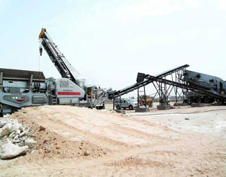
Liquid contract manufacturing, formulating, blending, and bottling of dishwashing detergents, cleaners, goods, health and beauty products, and custom chemical formulations. 35-gallon to 1,500-gallon batch sizes and various viscosity levels utilizing variable-speed, high-torque mixers.
WhatsAppGet PriceGet A Quote
see the simplified flow sheet in Appendix A, Flow Chart of Processes. Each year, an estimated 35,000 wells are hydraulically-fractured in the U.S. 1 Although the oil and gas extraction industry as a whole has a relatively higher fatality rate compared to most of the U.S. general industry (see Appendix B), there is currently no worker
WhatsAppGet PriceGet A Quote
Silica sand forms an essential component in the production of glass containers, flat glass, and speciality glass that are further used in automotive, construction and solar applications. The glass industry is followed by foundry, hydraulic fracturing, filtration , abrasives and others.
WhatsAppGet PriceGet A Quote
Flow Chart and Manufacturing Procedure of Dextromethorphan Hydrobromide, Chlorphenamine Maleate & Phenylephrine Hydrochloride Flavoured Dispersible Tablets Pharmaceutical Guidanace November 27, 2018 Production , Other Topic Comments Off on Flow Chart and Manufacturing Procedure of Dextromethorphan Hydrobromide, Chlorphenamine Maleate & Phenylephrine Hydrochloride Flavoured Dispersible Tablets
WhatsAppGet PriceGet A Quote
Cement Manufacturing Process Flow Chart. Clinker is first produced in a kiln system from silica fume and burnt shale. 90-150 kWh/t cement are
WhatsAppGet PriceGet A Quote
Silica is typically received in the form of metallurgical grade gravel. This gravel is 99.5% silica, and is 3 x 1 or 6 x 1 in (8 x 3 cm or 15 x 3 cm) in size. The coal is usually of low ash content (1-3% to minimize calcium, aluminum, and iron impurities), contains around 60% carbon, and is sized to match that of the gravel.
WhatsAppGet PriceGet A Quote
PROCESS FLOW DIAGRAM. 7. STEPS INVOLVED IN THE PRODUCTION OF NA2CO3 /NAHCO3 BY SOLVAY PROCESS 1- Ammonia absorption Saturation of salt solution with ammonia bubble and cap absorber. 8. 1.Trayed towers (plate columns). 2.Packed columns. 9. perforated valve cap Bubble cap. 10.
WhatsAppGet PriceGet A Quote
A general flow chart for sol-gel process which leads to the production silica using silicon alkoxides (Si(OR) 4) is shown in Figure 2. Figure 2 Flow chart of a typical sol-gel process.
WhatsAppGet PriceGet A Quote
Flow at surface will remain in mist flow until the conditions change sufficiently at the surface so that the flow exhibits a more liquid rich regime such as slug flow. At this point, the well production will be observed to become somewhat erratic, progressing to slug flow as gas rate continues to decline.
WhatsAppGet PriceGet A Quote
A flow chart of the experimental procedures for the production of highly pure mesoporous silica from hexaflurosilicic acid as a waste material of phosphate fertilizer industry.
WhatsAppGet PriceGet A Quote
Silica sand mining process equipment flow process Crushing processing sandstone sandstone crushing processing technology at present mainly has the following kinds. 1, crushing process directly.Its technological process is: the run of mine ore – grizzly – jaw crusher crushing and screening to cone crushing and screening, more paragraphs to roll the crushing and screening – products.
WhatsAppGet PriceGet A Quote
Isolating silicon from silica is the first step in the production of silicone. This is done by heating a large volume of quartz sand to temperatures as high as 1800˚C. The result is pure, isolated silicon, which is allowed to cool and then ground into a fine powder. To make silicone, this fine silicon powder is combined with methyl chloride
WhatsAppGet PriceGet A Quote
 WhatsAPP 24h online service


 24h Online Chat


